Sigfox Base Station Reverse Engineering - Part 1: Overview
Over a year ago I obtained a Sigfox base station, or TAP (Transfox Access Point), from a company that was moving and wanted to get rid of some of their old equipment. Sigfox operates a LPWAN (Low-Power Wide-Area Network), more-or-less as a competitor to LTE Cat. M/NB-IoT or LoRaWAN. I don’t think it ever achieved widespread adoption (in my experience - admittedly US-centric with a little experience in the UK and EU markets - Cat. M and NB-IoT have become more-or-less the dominant technologies in this space, due to their wide availability), though they are still around (since 2010) so must have had success in some markets.
I’ve been wanting to reverse-engineer and potentially repurpose this hardware for a while, but I haven’t gotten to it until now. I haven’t been able to find much info at all on the internet about the TAP, aside from some FCC filings which don’t really contain much (Sigfox provided a Letter of Confidentiality to prevent the FCC from publishing the schematics, block diagrams, operational descriptions, and internal photos - I typically expect those first three to not be published, but internal photos are more hit-or-miss).
Sidetracked: Older Sigfox products
While looking into this Sigfox hardware, I stumbled upon some other products that Sigfox used to sell, presumably before they started fully focusing on LPWAN. There is very little info about these products around anymore. I first found out about the Transfox SDR after looking for more info on the TAP (I found the acronym defined in some FCC filing, if I recall) and found this product sheet. This in turn held a mention of the SynFox synthesizer, which I found some more info about here. I also found this page that mentioned the SynFox, and linked to Sigfox’s old website (sigfox-system.com).
sigfox-system.com is no longer around, and it was not well-preserved by the Internet Archive. It seems like all of it’s pages do not display properly - at first I thought that the archive hadn’t stored any real pages at all, they just appeared blank. However, digging into the source I realized there was some actual content there. For instance, this page shows as blank (minus the Internet Archive toolbar), but if I look at the source I do see the links. Unfortunately, all these links point to tera-concept.com, and none of them are archived (presumably TERA CONCEPT developed/helped develop the hardware/software for some of Sigfox’s earlier products).
Their website was also peppered with Lorem Ipsum, so it was definitely in the start-up stage.
It also shows existence of yet another Sigfox product, the BlueFox. Confusingly, there is also a more recent device called the BlueFox by Net Sensors that uses a Sigfox radio, but is seemingly unrelated to this original BlueFox. According to their website (translated from French):
“BlueFox” 2.4 GHz “long range” USB radio module. The BlueFox “long range” 2.4 GHz USB radio module, allowing robust data transmission at 1 Mbit/s, over distances of 100 m to 20 km depending on the installation.
SynFox: Coverage, precision, speed and low noise at a price never seen before!
There is also a 20W RF power amplifier, and another 2-4W RF amplifier. It seems they did sell to hobbiests/hams, a bit of a shame they left that market.
Overview of the TAP
I won’t be going too in-depth in this post, just giving a higher-level overview of the internals of the device. I will write up more posts in the future that go more in depth into some of the components.
Outside
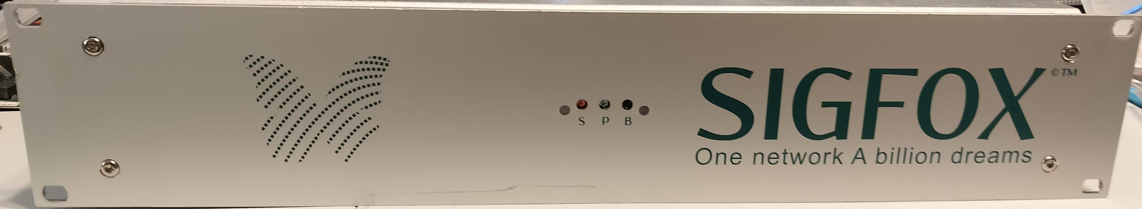
The device is mostly self-contained. It has two LEDs (status and power), and a “service mode” button used for power control on the front.
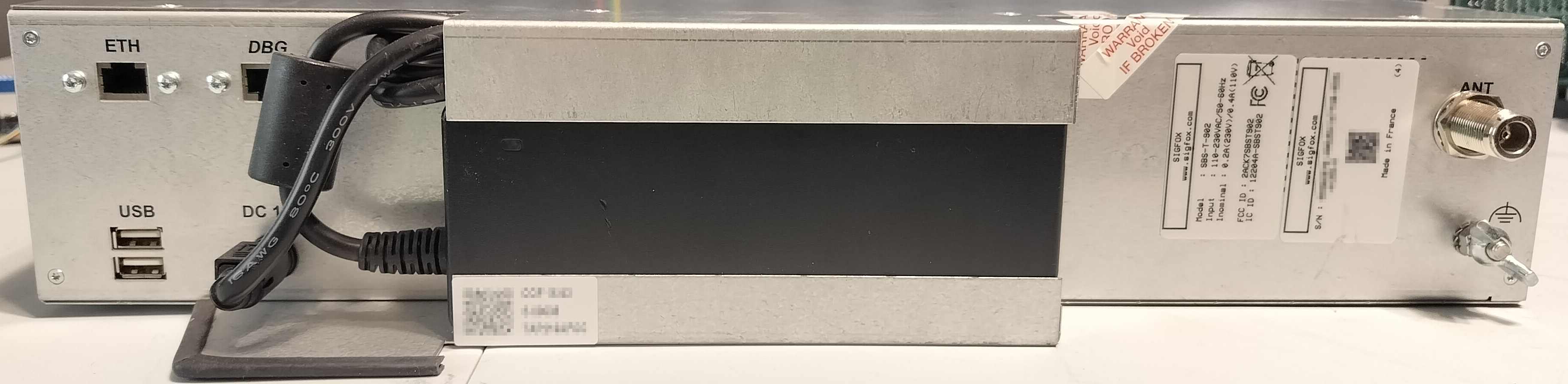
Around back, there is an Ethernet jack for network connectivity, and another RJ45 for serial console (unsure if this is the standard Cisco-style pinout or not, as I have just used the internal DE-9). Under that, there are two USB ports (one intended use of which is connection a cellular modem), and the power input that is fed by a semi-integrated power brick. On the other side, there is an N connector that goes out to the antenna (and LNA and/or filter).
Inside
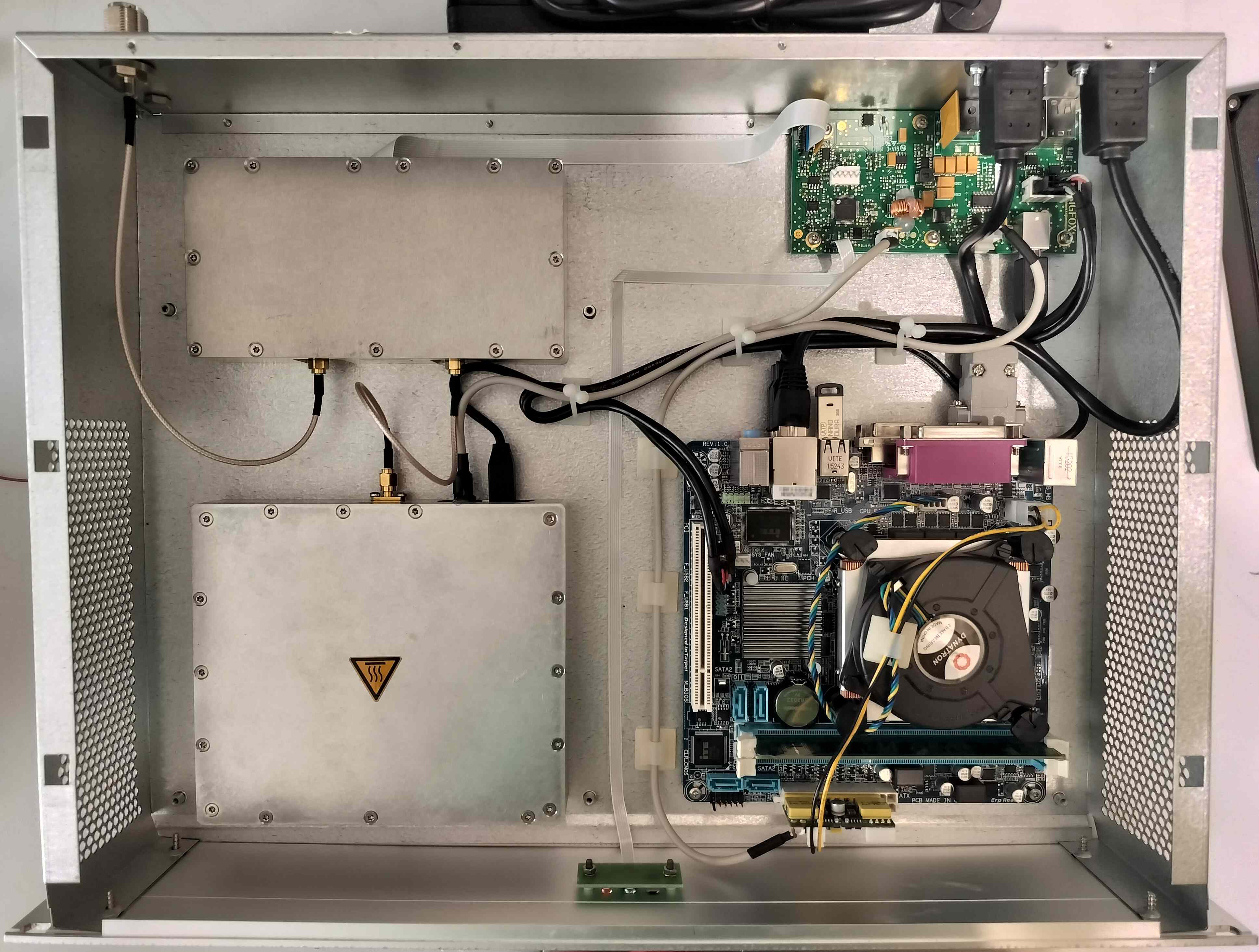
Inside the unit, we find that it is all powered by a standard x86 computer. There is a custom board for power and some I/O, and two enclosed RF units. One is connected to the PC via USB, and one is connected via a ribbon cable to the power and I/O board.
Motherboard
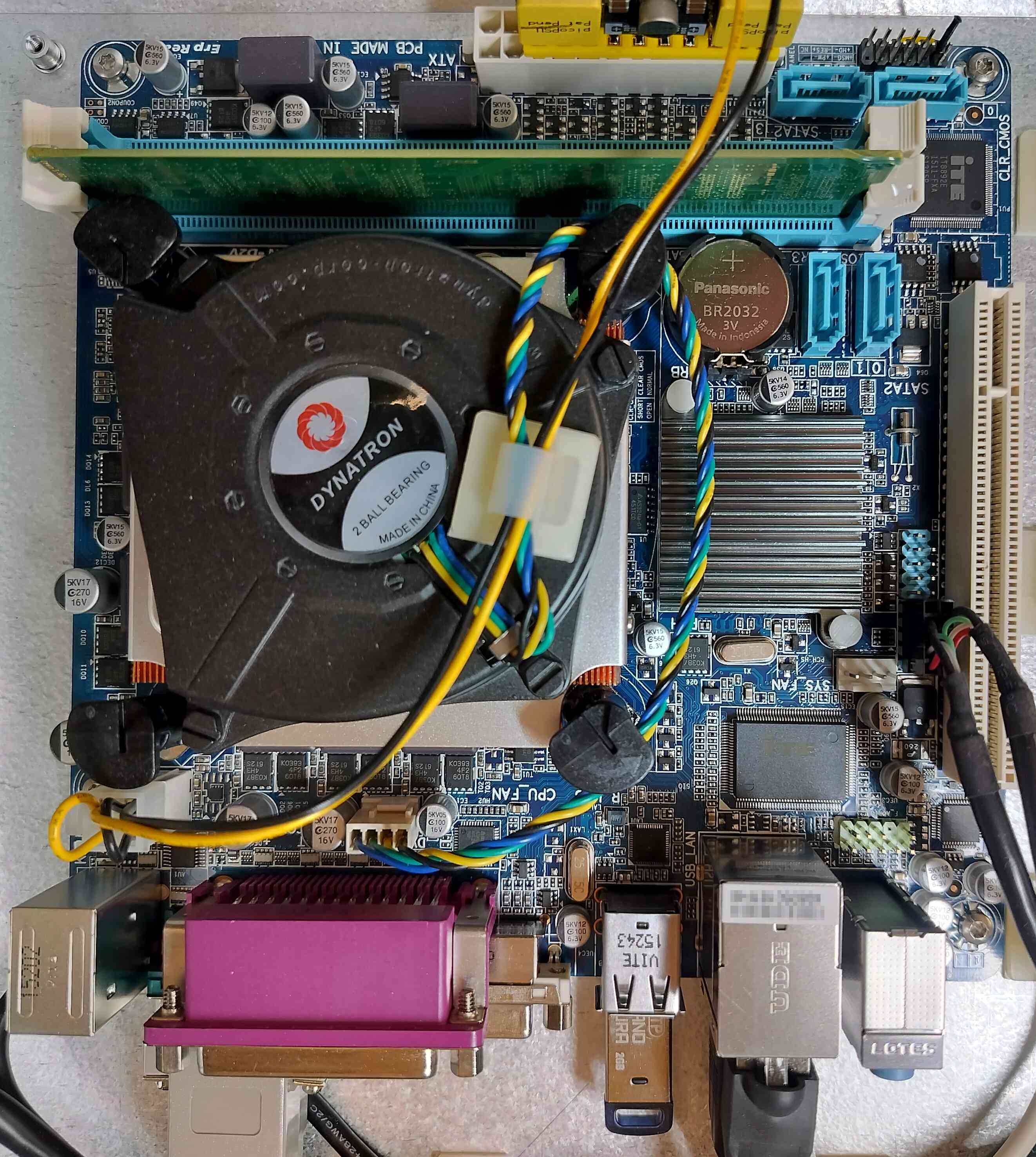
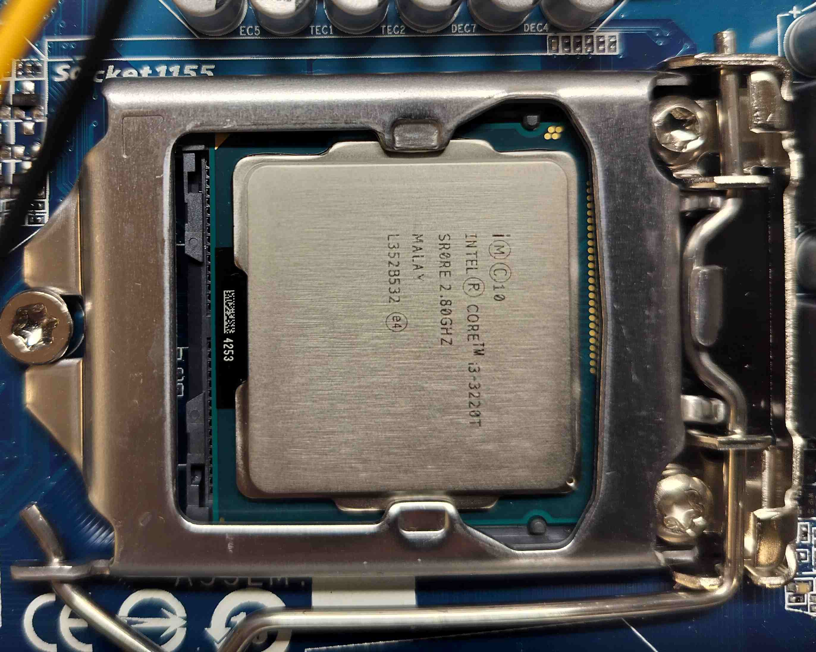
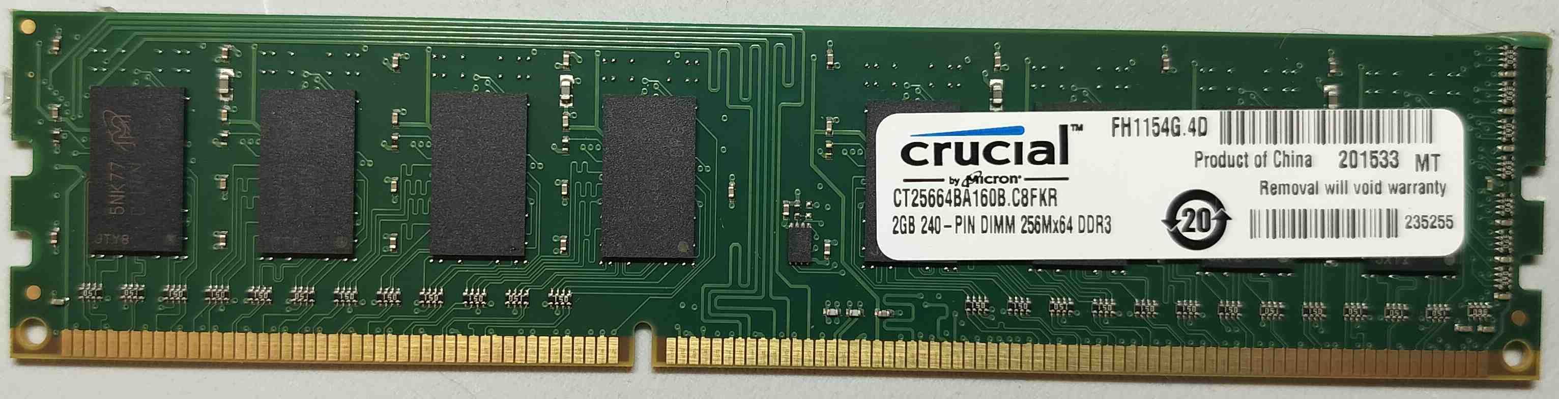
The motherboard is a fairly standard (mini ITX?) board, with an Intel i3 3220T (a low-TDP/low-clock variant of a 3220), and 2 GiB DDR3 RAM (the tabs for which were held in place using hot glue).
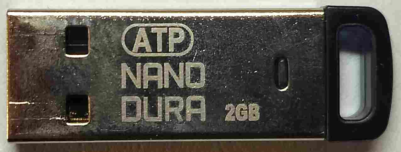
The OS is stored on an ATP USB drive intended for high-reliability and industrial applications. The device is simply running Linux 3.8.13. I may investigate the system deeper as I look more into the SDR hardware.
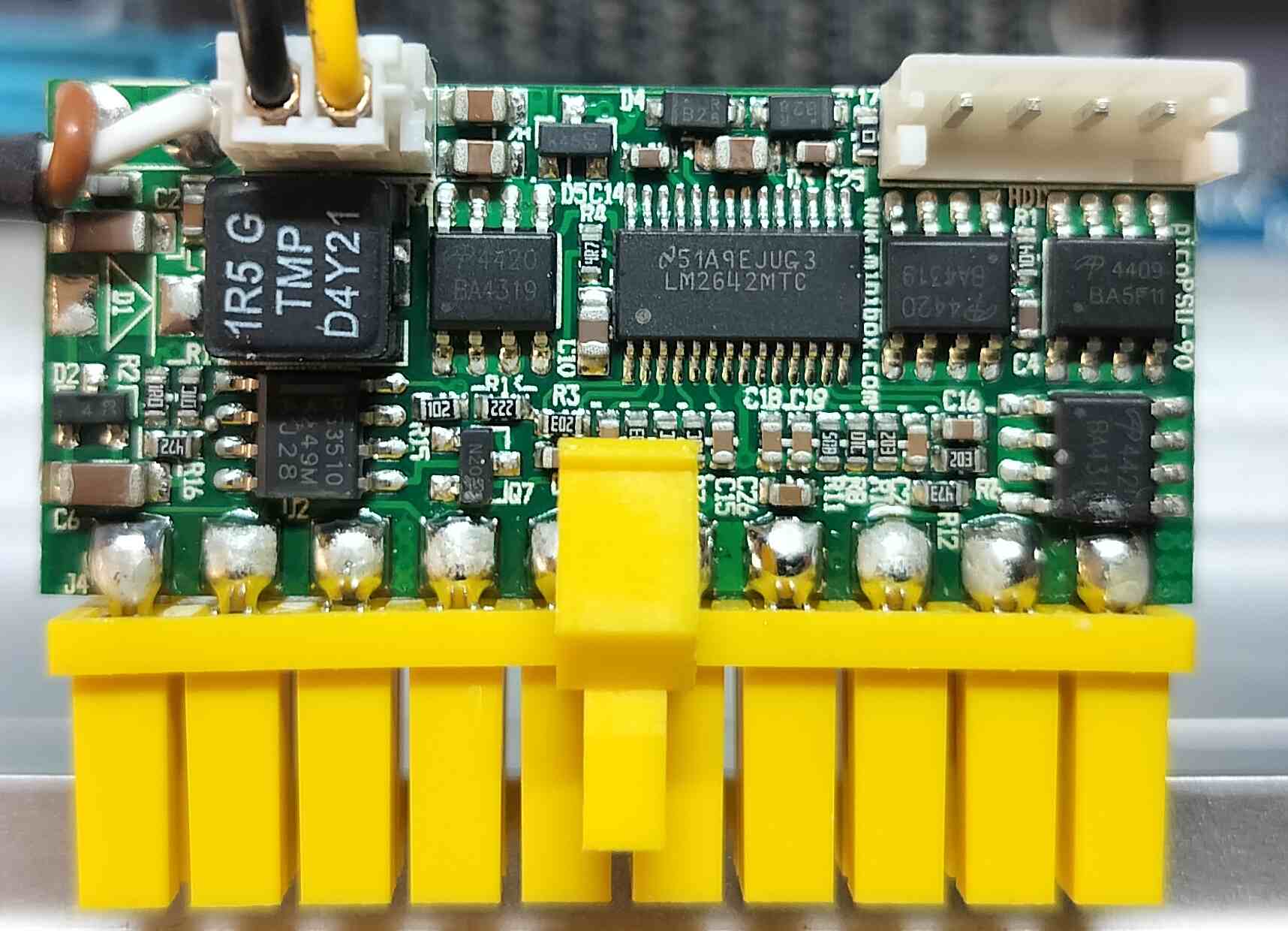
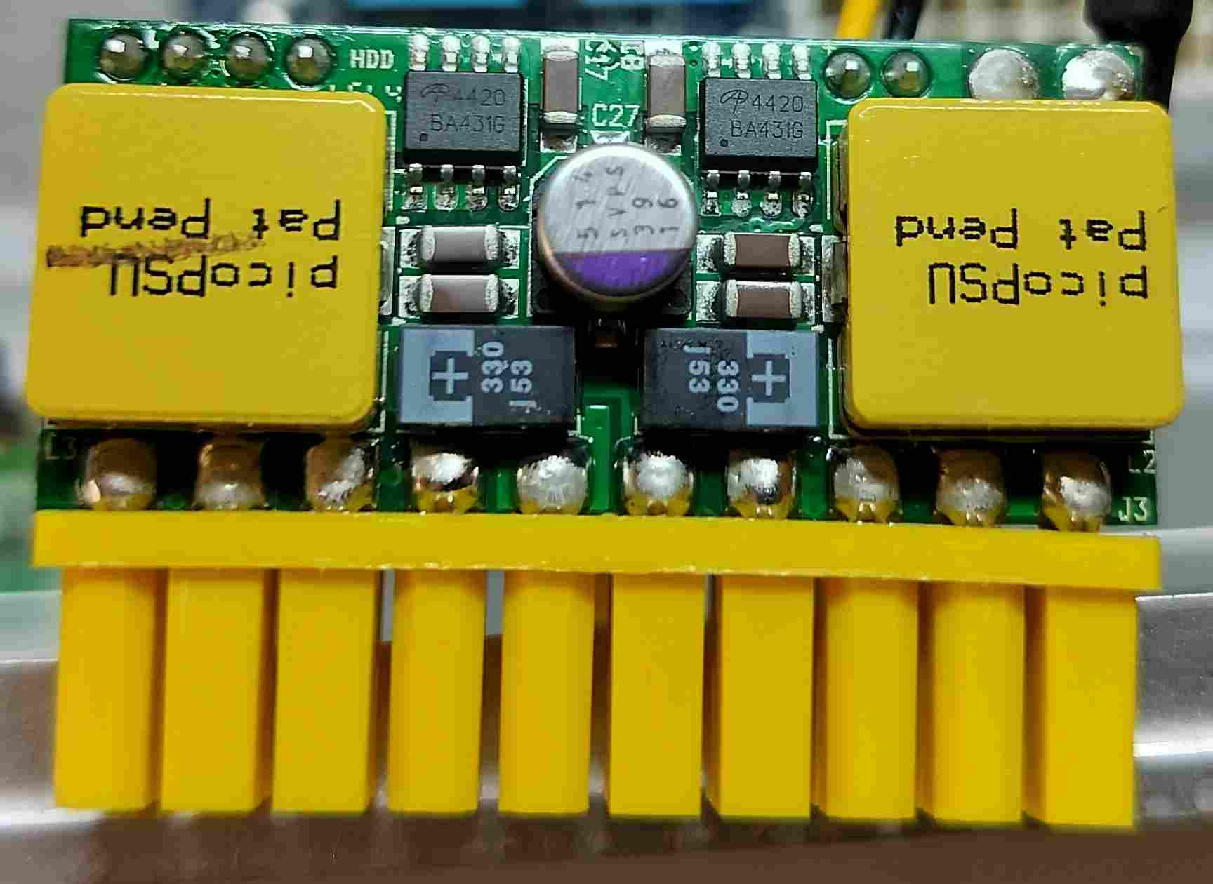
The motherboard is powered by a PicoPSU, which is in turn connected to the custom power board.
BRE: Power and I/O board
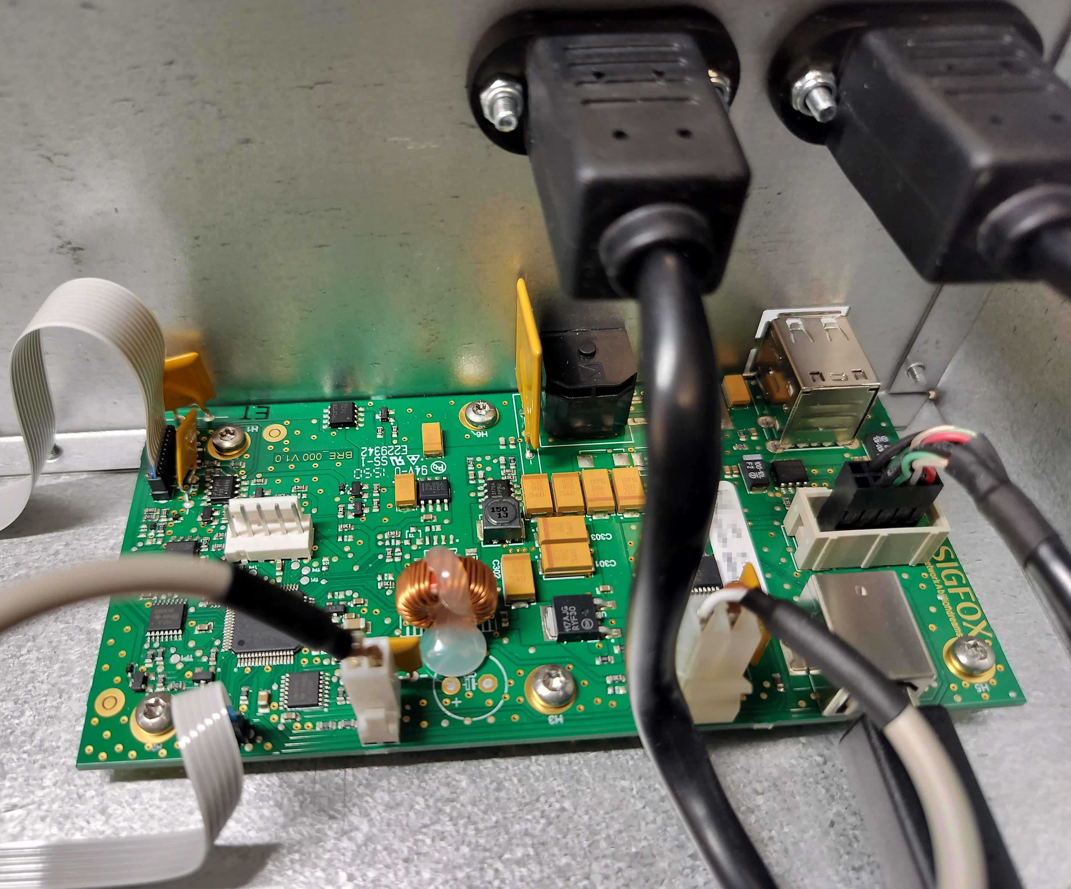
At the rear of the chassis there is a board that handles the incoming power, and also includes a handful of I/Os. Here is an overview of what it handles:
- Power to the motherboard
- Power to the SDR module
- The two USB ports on the back of the chassis
- The front panel LEDs and switch
- Power and control for the power amplifier module
It includes a PIC18 that presumably handles all the I/O functionality, and an FT232R that is likely used to communicate with the PIC18. I will probably take a closer look at these in a future post.
RF modules
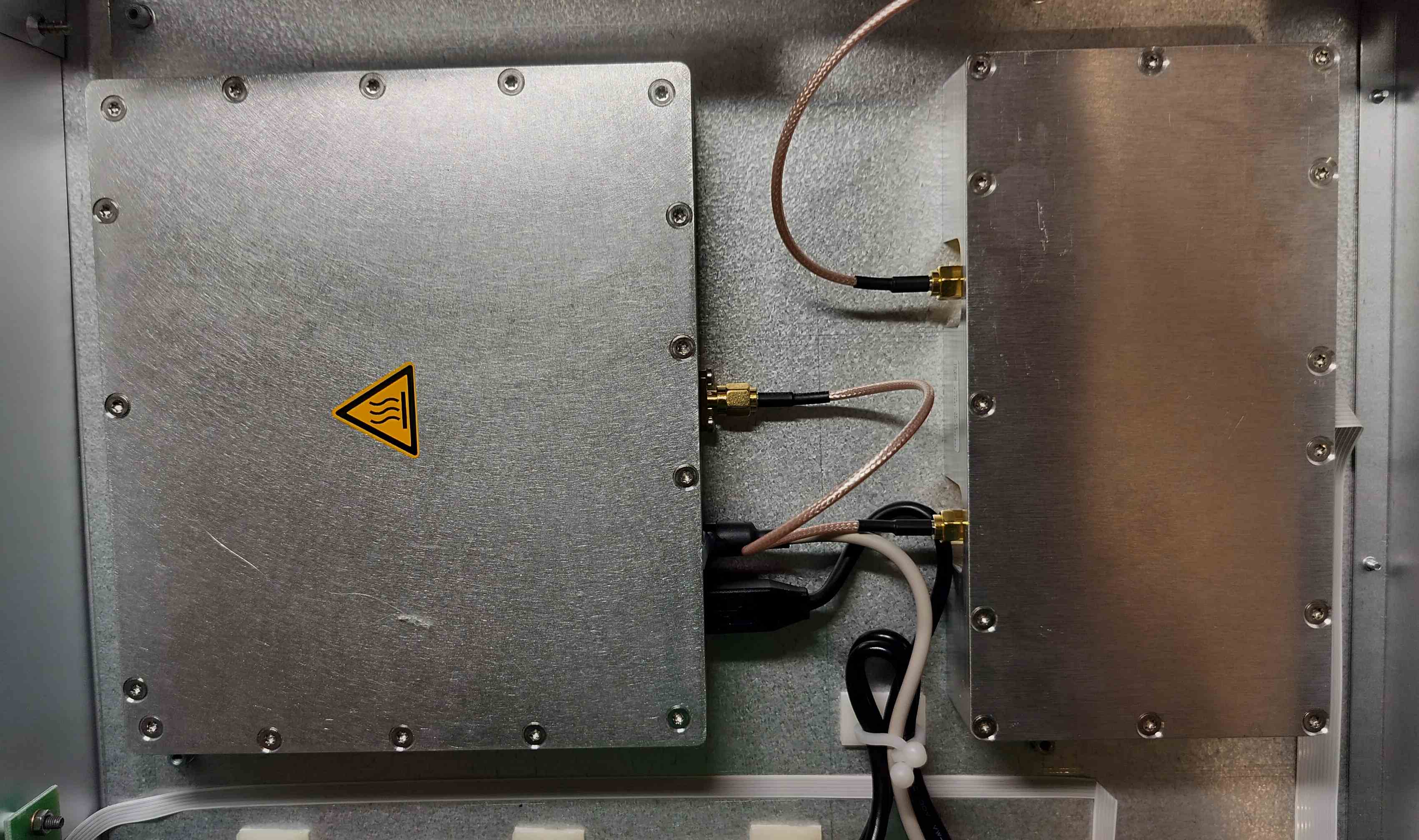
I will save the RF modules for another time, as I want to go much more in-depth on them, especially the SDR. For now, I will say the one near the front (with the heat warning) is an SDR (based partially on a USB audio interface). The other modules is a power amplifier. The SDR communicates directly with the computer over USB, while the LNA is only connected to the BRE board via a ribbon cable.
LNA, Filter, and Antenna
Along with the base unit, I also got the external equipment that went with it.
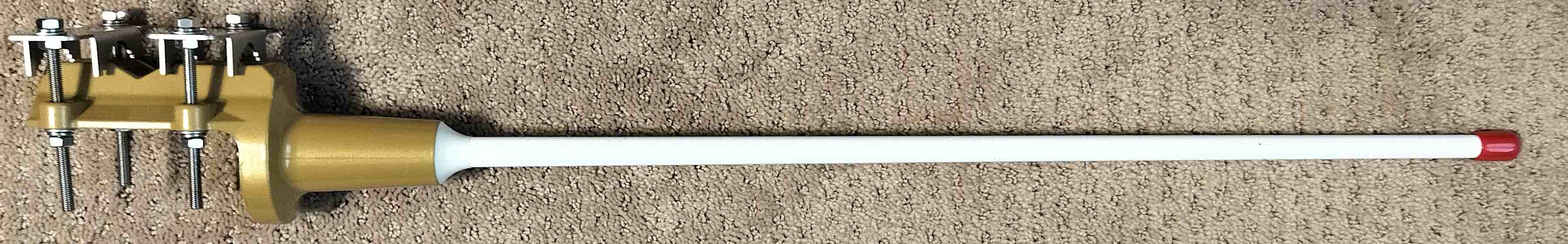
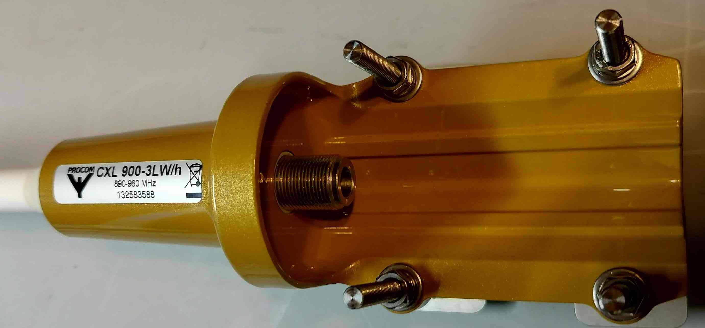
The antenna is a PROCOM CXL 900 3LW/h, a pretty basic whip antenna covering 890~960 MHz (I didn’t get around to actually measuring it).


There was also a cavity filter it came with, centered about 905 MHz.
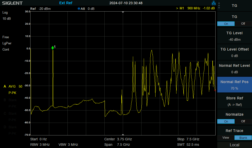
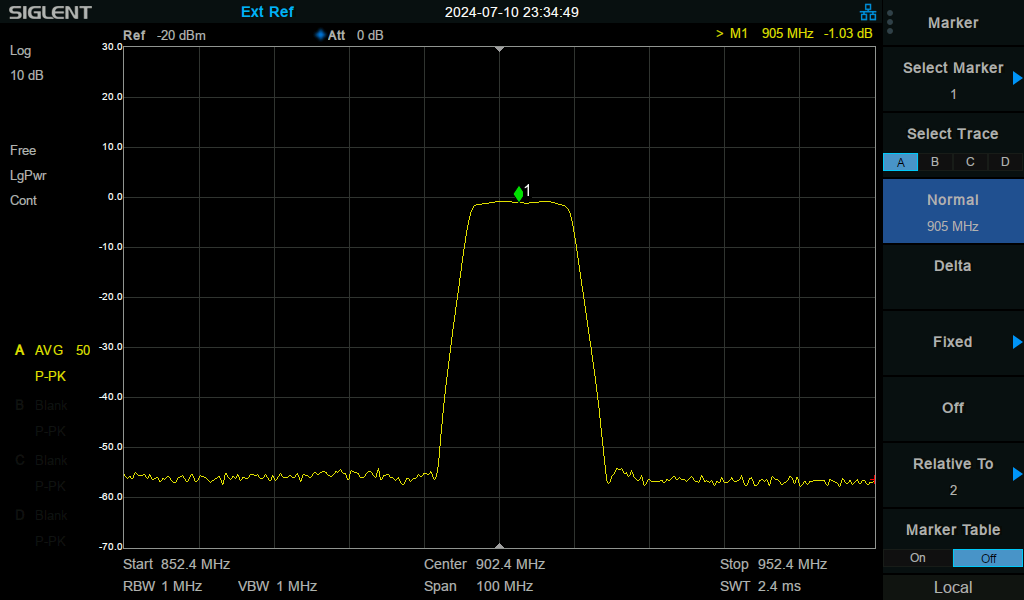
I did take some measurements of this one. It was pretty spot on (even after taking it apart and putting it back together), and covered approximately 898-912 MHz.

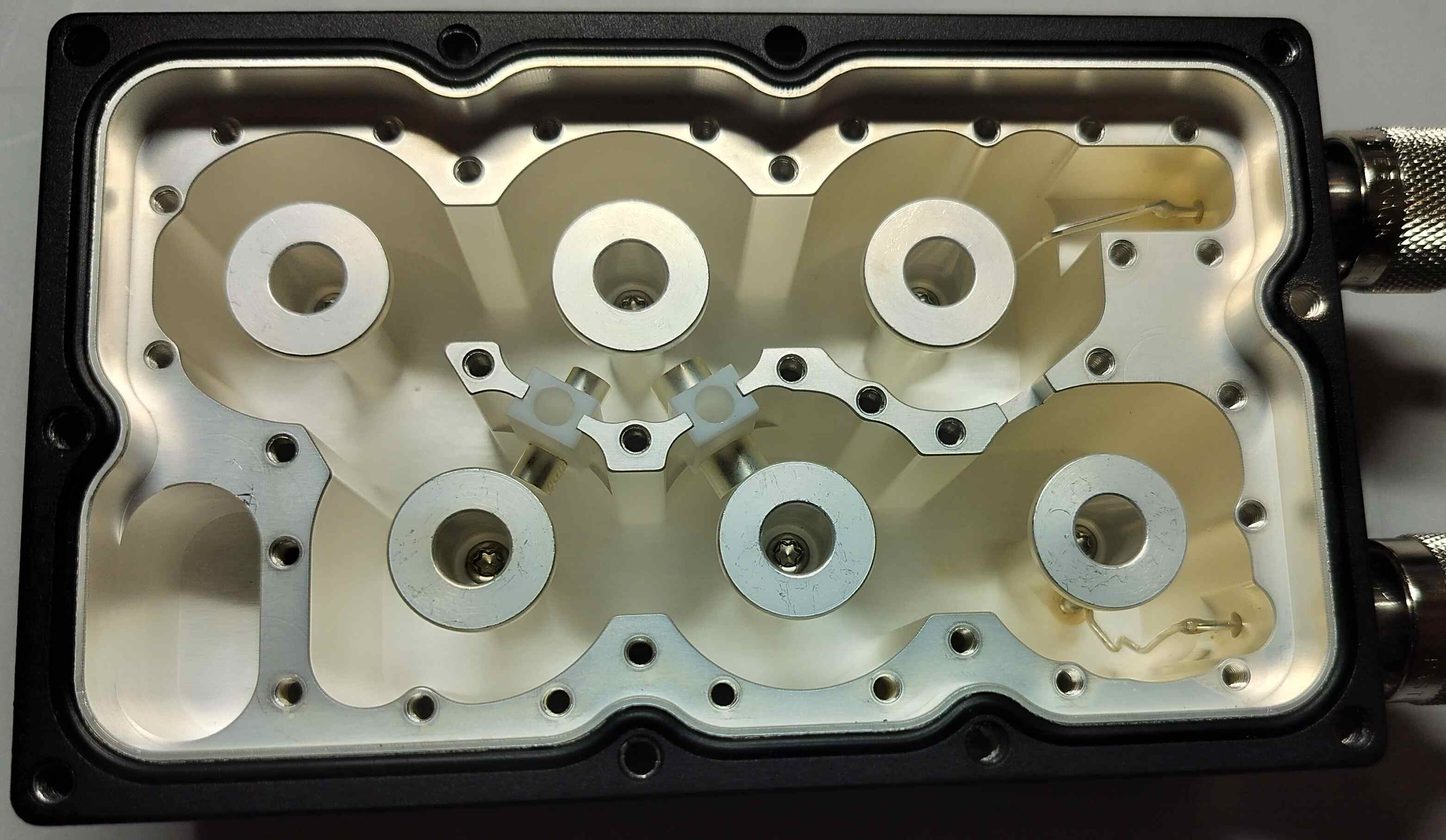

The internal RF magic. The screws in the sub-cover protrude into the cavities underneath it, and are used for tuning.
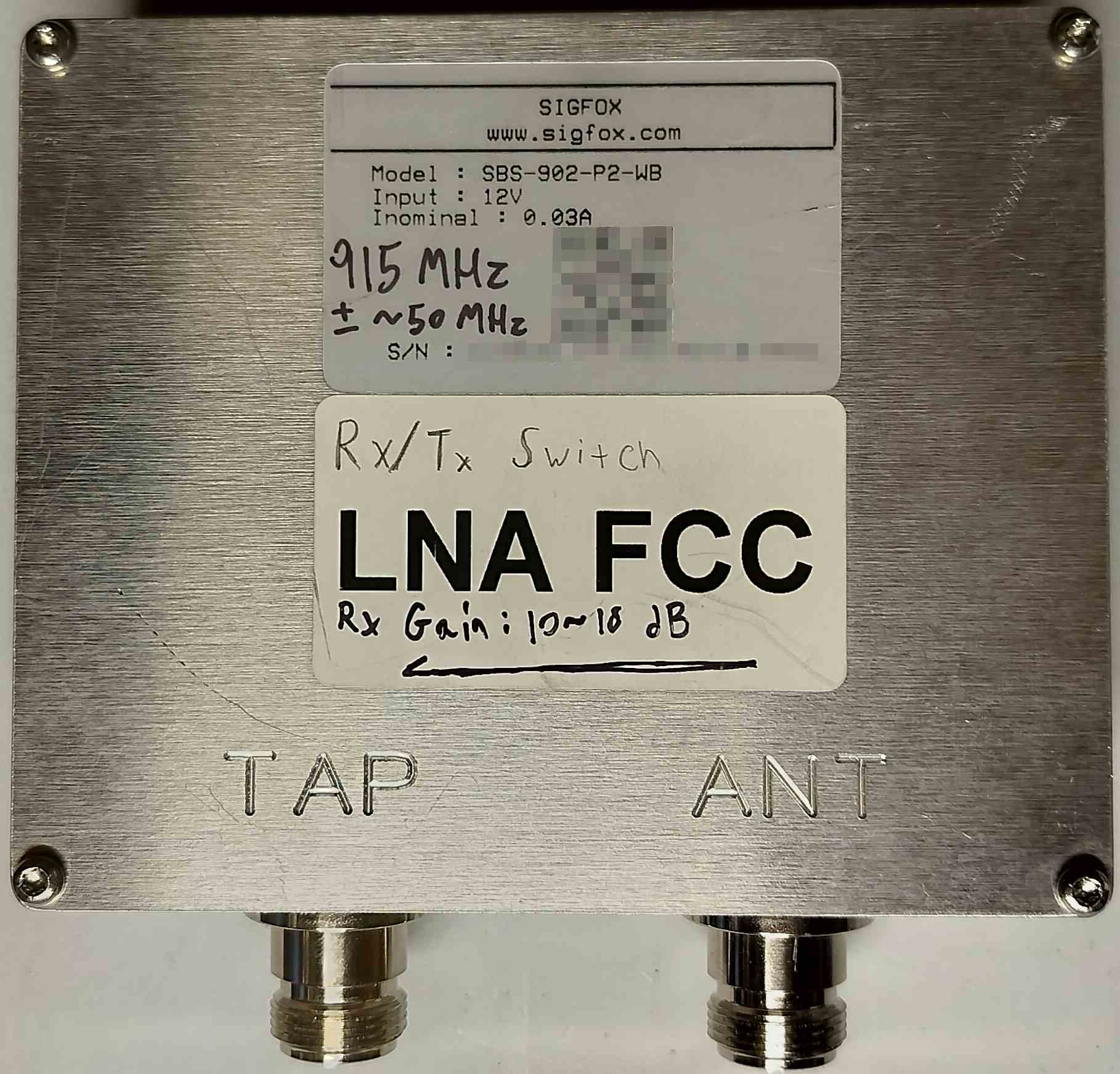
I plan on doing a more thorough analysis of the LNA, so for now here is the exterior. It’s job is to amplify incoming signals, and passing through outgoing signals.
To be continued
I will start writing up more specific posts for some of the components in the coming weeks, months, or whenever I get around to it.