Tektronix TLA Logic Probe Leadset Replacement
GitHub repo containing the PCBs and 3D models in this post: https://github.com/farlepet/tek-tla-probes
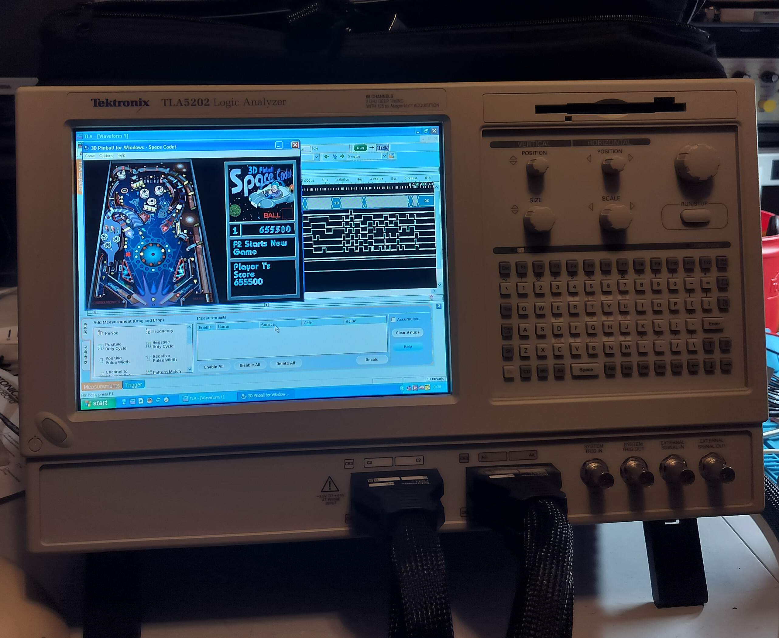
A while back I got a Tektronix TLA5202 logic analyzer, as I wanted a standalone unit I could use without needing to fiddle around with connecting a USB logic analyzer to a computer/laptop and dealing with the occasional instability of PulseView. Not that this isn’t in reality a computer connected to a logic analyzer internally, but at least it’s in a single package and always ready at by bench.
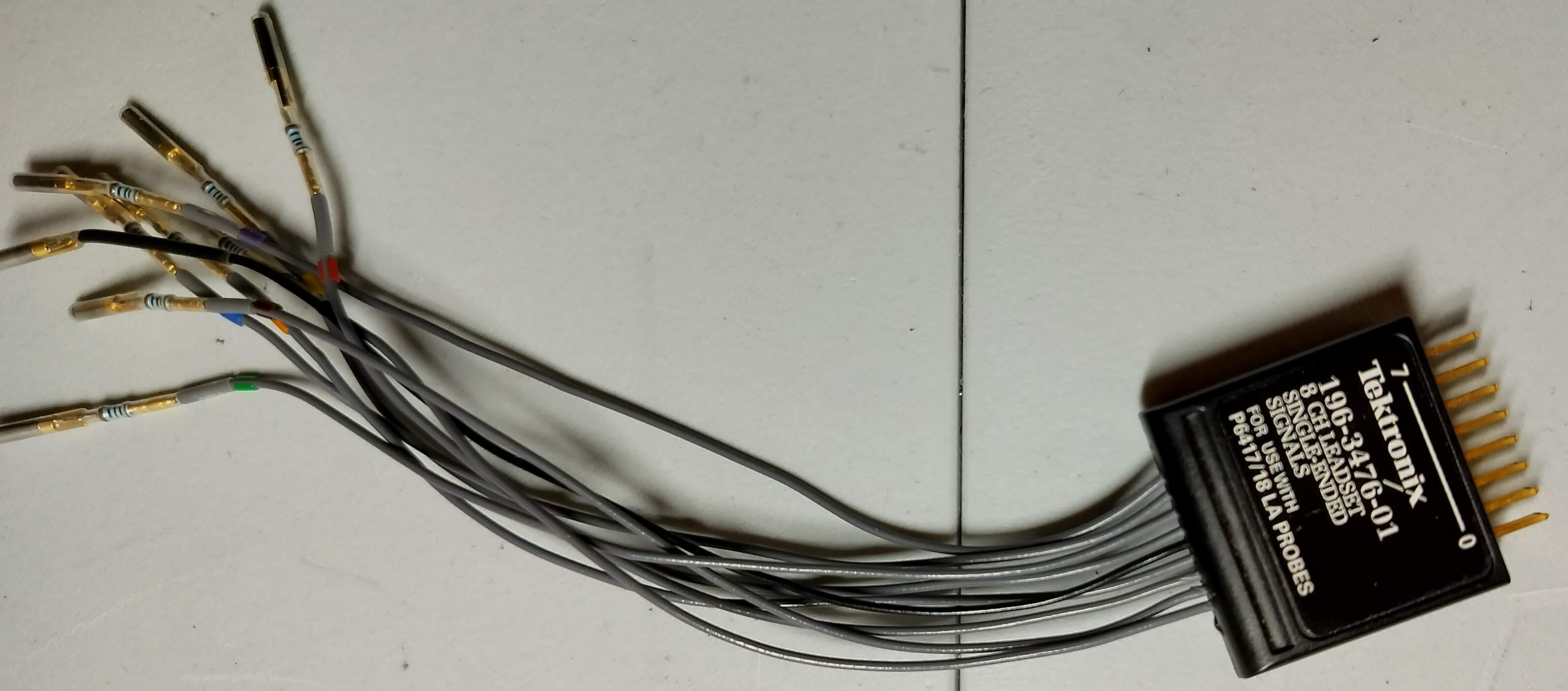
For the logic probes, it came with a single probe cable (a P6417) and two leadsets (196-3476-01). The cable itself breaks out into two sets of 8 connectors (data + ground), plus an additional clock input. For convenience, each set of 8 connectors can be combined using included clips, creating a .1” 2x8 socket array. They then also provide leadsets that have a 2x8 male connector that mates with these, and provides a set of flying leads plus a ground. These leads also each have a 100 Ω resistor right before the end of the jumper, to improve signal integrity/response.
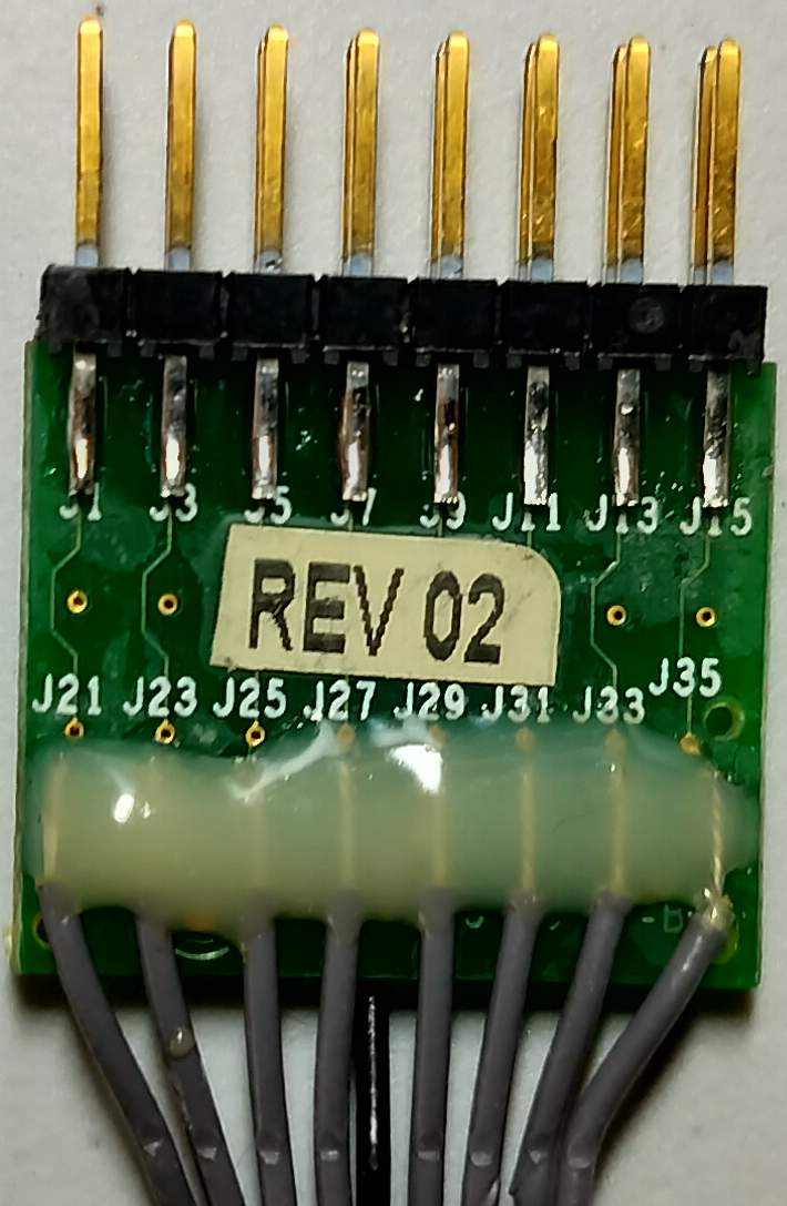
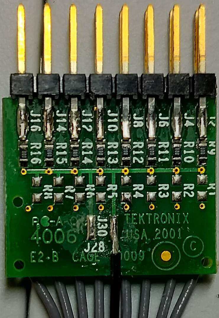
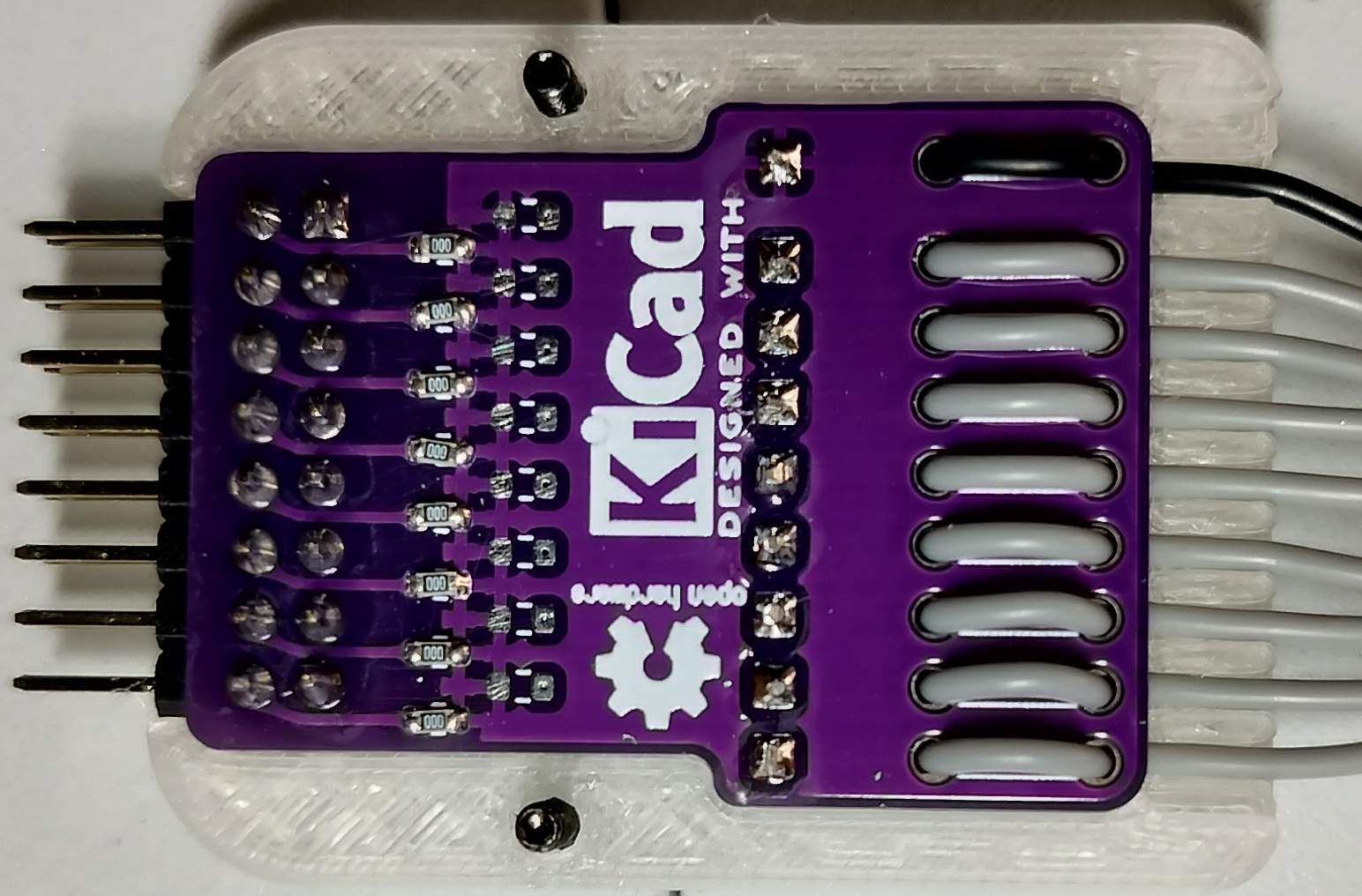
I also cracked one open, as I was curious if there was anything special inside (there wasn’t, it was just a PCB with some 0 Ω resistors):
Since the logic analyzer had 64 channels, I wanted to get more cables and leadsets to be able to utilize them all (in the unlikely even that ever happens). The cables were relatively inexpensive used, but the leadsets were more than I was willing to spend on what was ultimately just a connector, some wires, resistors, and fancy female connectors - the ones I found were going for more than $30 a piece - which would be nearly $200 just for the leadsets alone.
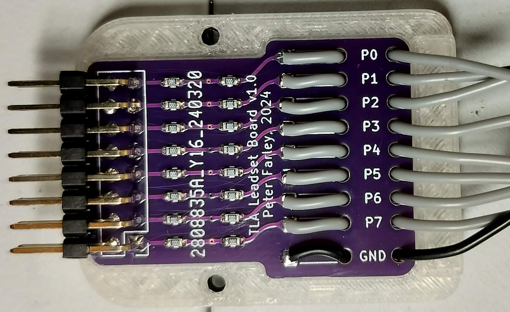
So instead of doing that, I decided to build my own. I could have just soldered some wires to a male .1” 2x8 connector and called it a day, but I wanted something a little more sturdy. It’s still pretty basic, but I designed a basic PCB that took a right-angle male header, and had some integrated strain-reliefs for the wires on the other end. Additionally, I added the ability to build a voltage-divider/attenuator into the leadset itself. By default, I would populate two resistors per channel with 0 Ω jumpers, but I could also change them to some other value and add a resistor to ground to create a T pad (or leave the probe side at 0 Ω to make a simple voltage divider). Not sure I’ll ever use that functionality, but 0 Ω jumpers are dirt cheap (though it does make assembly take longer).
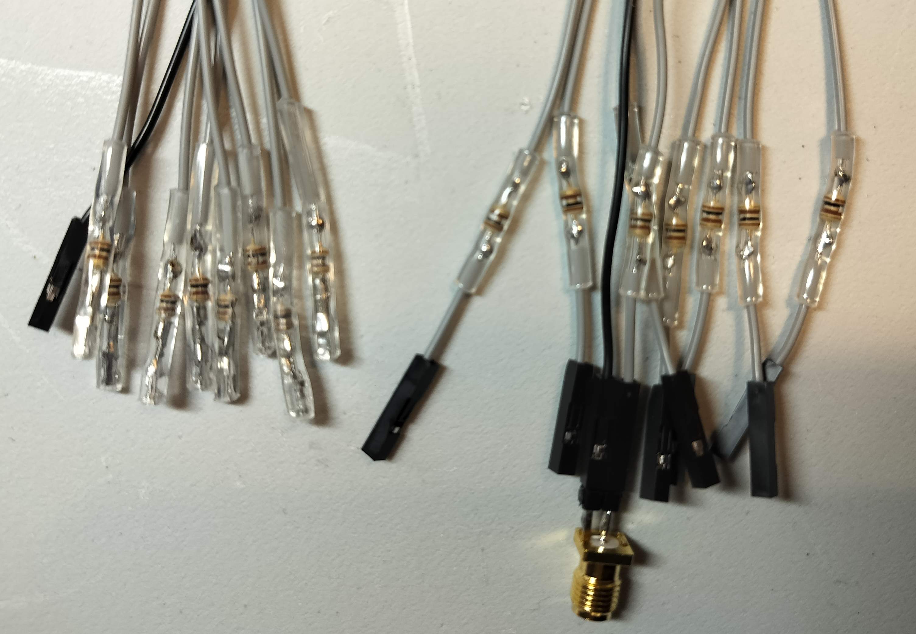
I tried two methods of adding the 100 Ω resistor at the ends of the probes. The first method was to try to do what Tektronix did on the original probes, and directly connect the resistors to the connector - in this case crimping the connector on to the resistor - and then using heat-shrink over it. The heat shrink I had on hand has a shrink ratio of 3:1, which I think was too much making the result too thick. It still worked well, but the connectors could be hard to use directly next to each-other, I may try it again if I get some 2:1 tubing. The second method was just splicing the resistor in the middle of the wire (though closer to the connector end) and crimping the connector on the wire as usual.
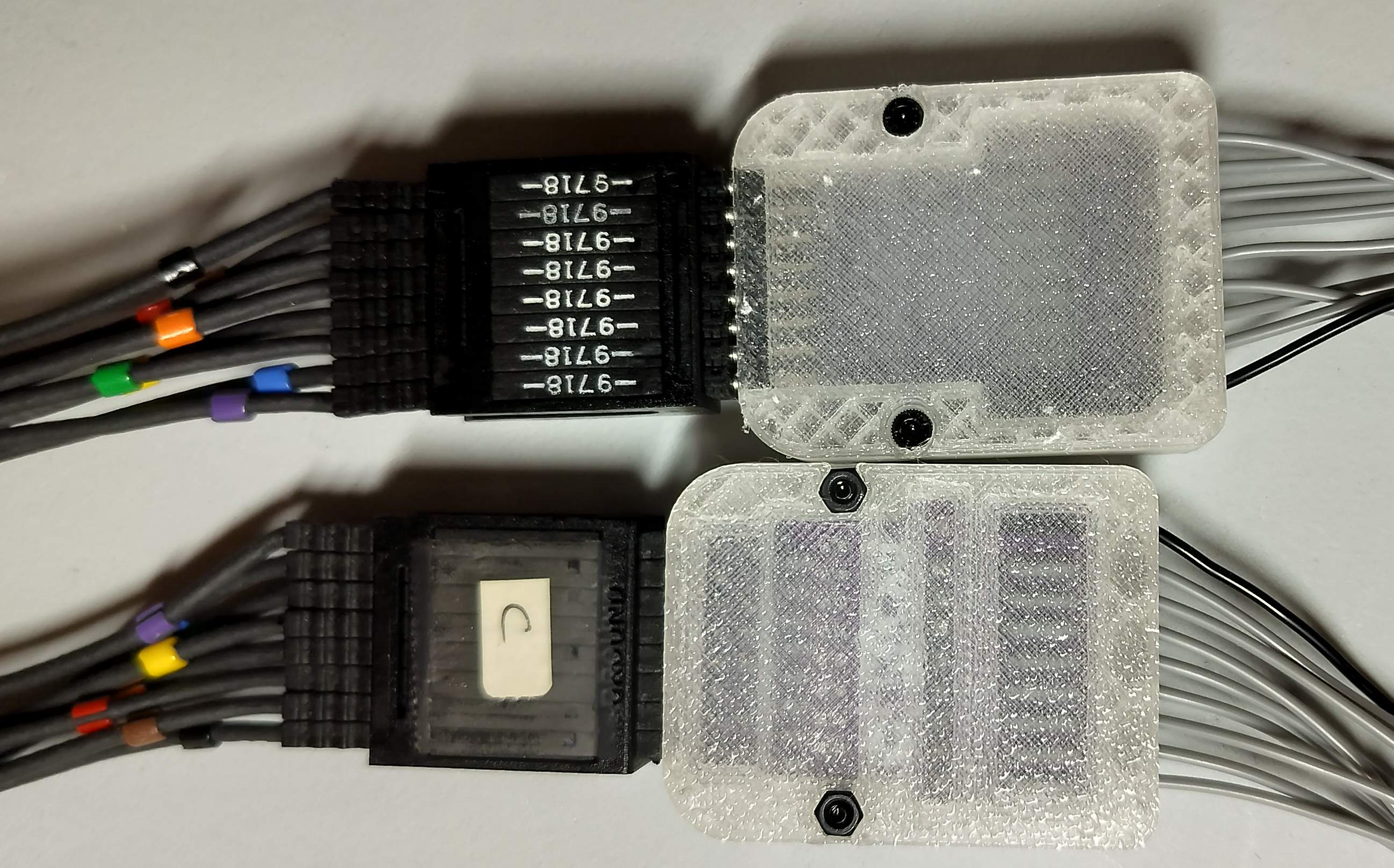
Once I confirmed the probes were working as expected, I designed a 3D-printed case for them, just to clean it up a little. At this point, I realized how much I rushed the PCB design - the spot at which the PCB widens is in a different location on either side. At least the enclosure made it less obvious (if I would have used opaque filament, it would be completely hidden).
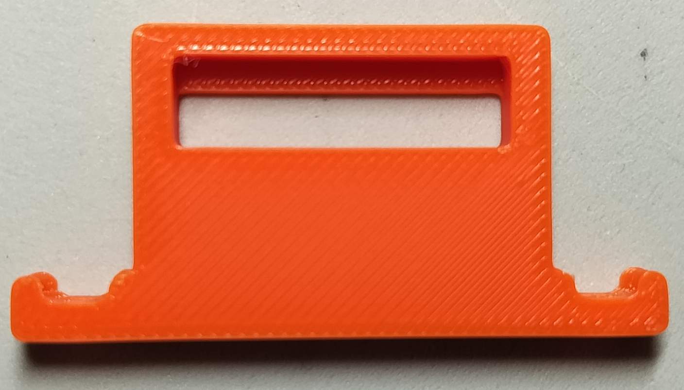
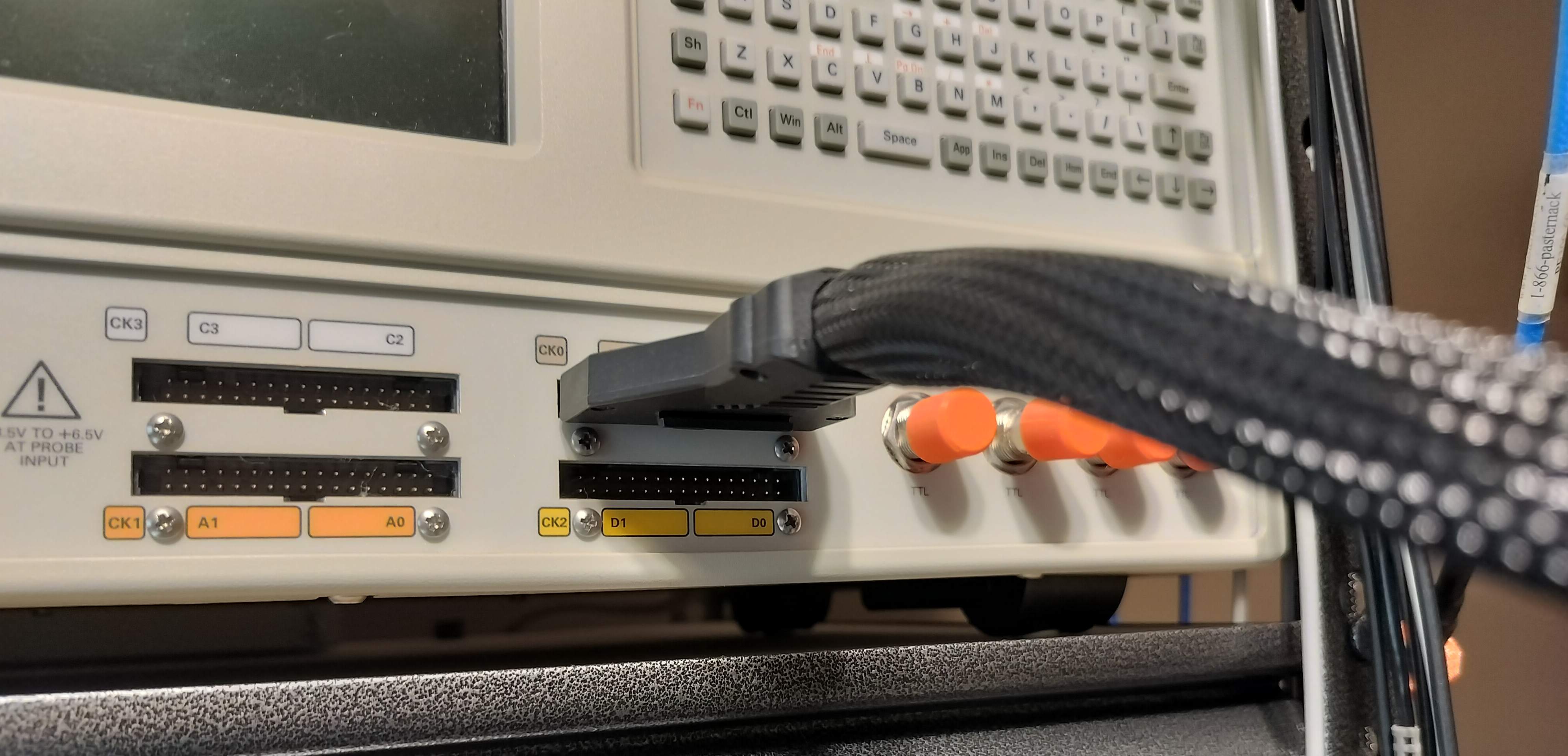
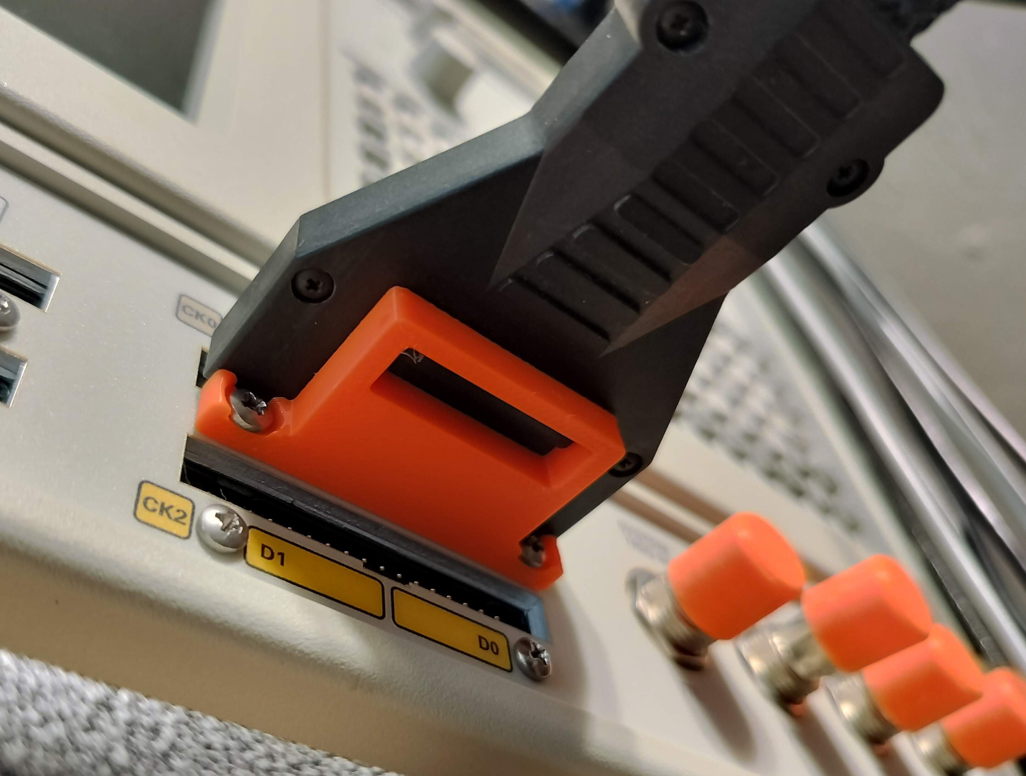
Finally, the probe cables also had a feature in the instrument-side connector that allowed it to be fastened to the machine with a bracket. None of my probes came with any of these brackets or screws, but the mechanism was pretty simple, so I also designed a printable replacement for those. (The original bracket would have been compatible with both the P6417 and the P6418 cables, though this one is only compatible with the former since it doesn’t have he proper cutouts for the screws that one uses).
As an aside, it always feels strange to me seeing some of these older higher-end machines just running stock Windows. And apparently newer scopes still do the same, with some running Windows 10 under the hood. Though these days, I think there is more of a trend towards Linux-based (and in some cases Android-based) systems, though I’m not sure if that’s also true for the higher end.
On the bright side, since this instrument runs stock Windows XP, it comes with 3D Pinball: